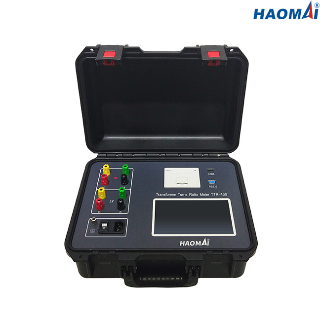
TTR-400
The TTR-400 is a portable transformer turns ratio meter that measures turns ratio, voltage ratio and phase displacement…
- Ratio range 0.9 – 10000
- Accuracy (by ratio range) ±0.1 % / ±0.2 % / ±0.5 %
- Test voltage 0 – 160

Eight-model family of 4-wire DC winding ohmmeters for power and distribution transformers, generator stators and circuit-breaker contacts — from a 5.28 kg 10 A instrument to the 100 A TWO-1100S, with 0.1 µΩ resolution and ±0.2 % reading accuracy across the range.
US$3,000/ set
| Specification | TWO-110 | TWO-110S | TWO-120 | TWO-140S | TWO-150S | TWO-160S | TWO-320 | TWO-1100S |
|---|---|---|---|---|---|---|---|---|
| Maximum DC test current | 10 A | 10 A | 20 A | 40 A | 50 A | 60 A | 20 A (3-phase) | 100 A |
| Current steps (top / count) | 10 / 5 A · 6 steps · auto | 10 / 5 A · 6 steps · auto | 20 / 10 A · 6 steps | 40 / 20 A · 6 steps | 50 / 20 A · 6 steps | 60 / 40 A · 6 steps | Automatic · up to 20 A | 100 / 50 A · 5 steps |
| Range at maximum current | 1 mΩ – 1.6 Ω | 0.5 mΩ – 0.8 Ω | 100 µΩ – 1 Ω | 50 µΩ – 500 mΩ | 50 µΩ – 400 mΩ | 40 µΩ – 300 mΩ | 0 – 100 Ω | 50 µΩ – 100 mΩ |
| Total resistance span | 1 mΩ – 100 kΩ | 0.5 mΩ – 100 kΩ | 100 µΩ – 100 kΩ | 50 µΩ – 20 kΩ | 50 µΩ – 20 kΩ | 40 µΩ – 20 kΩ | 0 – 100 Ω | 50 µΩ – 4 Ω |
| Measuring accuracy | ±0.2 % rdg ± 2 µΩ | ±0.2 % rdg ± 2 µΩ | ±0.2 % rdg ± 2 µΩ | ±0.2 % rdg ± 2 µΩ | ±0.2 % rdg ± 2 µΩ | ±0.2 % rdg ± 2 µΩ | ±0.2 % rdg ± 2 µΩ | ±0.2 % rdg ± 2 µΩ |
| Resolution µΩ | 0.1 | 0.1 | 0.1 | 0.1 | 0.1 | 0.1 | 0.1 | 0.1 |
| Display | LCD screen | 7 in high-brightness touch screen | 7 in true-colour LCD | 320 × 240 colour LCD | 320 × 240 colour LCD | 320 × 240 colour LCD | 7 in true-colour LCD | 320 × 240 colour LCD |
| Result storage groups | > 300 | 1000 | 500 | 1000 | 1000 | 1000 | 500 | 1000 |
| Dimensions (mm) mm | 327 × 270 × 140 | 360 × 290 × 170 | 400 × 340 × 195 | 400 × 225 × 350 | 400 × 225 × 350 | 400 × 225 × 350 | 400 × 340 × 195 | 400 × 225 × 350 |
| Weight kg | 5.28 | 6 | 8.6 | 13 | 15.1 | 15.1 | 8 | 19.5 |
All eight models share the 4-wire Kelvin method, ±0.2 % reading ± 2 µΩ accuracy, 0.1 µΩ resolution, USB download, built-in printer, IEC 61010-1 safety design and IEC 61326 EMC. They differ in maximum test current, resistance coverage, display, storage and weight. Highest-specification model: TWO-1100S at 100 A.
The TWO Series is a family of eight 4-wire DC winding ohmmeters for measuring the DC resistance of power-transformer, distribution-transformer, generator and motor windings. All eight models share the same measurement principle, accuracy, resolution, printer and USB interface; they differ in maximum test current, resistance coverage, display and weight. The TWO-1100S at the top of the range delivers up to 100 A — the highest test current in the family — for the lowest-resistance windings, while the 10 A TWO-110 / TWO-110S reach to 100 kΩ for high-resistance windings at a carry weight of 5.3–6 kg.
A transformer winding ohmmeter — also described as a winding resistance tester, DC resistance tester or micro-ohmmeter — injects a stabilised DC current into a winding through one pair of leads and senses the voltage drop across it through a second pair, so that the resistance of the test leads is excluded from the result. The measurement is the basis of transformer acceptance testing, factory routine testing and field diagnostics.
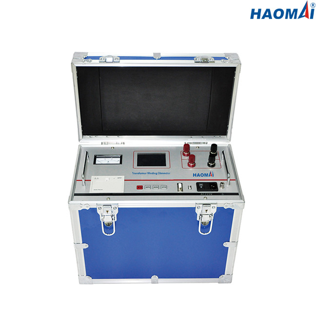
Winding resistance is a routine measurement on every transformer, at the factory and on site. Comparing phase-to-phase and tap-to-tap readings exposes faults that other tests can miss:
Because the values of interest sit between a few micro-ohms and tens of ohms, the measurement has to be four-wire, and the test current has to be high enough to bring the inductive winding into a stable magnetic state before the reading is taken.
Select by the expected winding resistance first, and by the required test current second. The 100 A model is not automatically the right choice: its 50 µΩ–4 Ω coverage is optimised for large, low-resistance windings, whereas a 10 A model covers up to 100 kΩ. Each current step has its own specified resistance range, and the highest current does not cover the whole span — see the model comparison table at the top of this page.
| Winding under test | Typical DC resistance | Typical current step |
|---|---|---|
| Distribution transformer, LV winding (up to about 1 MVA) | 0.5 mΩ – 50 mΩ | 10 – 100 A |
| Distribution transformer, HV winding | 50 mΩ – 5 Ω | 2 – 10 A |
| Power transformer, 110 kV winding | 0.2 Ω – 3 Ω | 5 – 20 A |
| Power transformer, 220 kV and above | 1 Ω – 20 Ω | 1 – 5 A |
| Generator or motor stator winding | 0.1 mΩ – 1 Ω | 10 – 100 A |
| Busbar, joints, contacts, circuit-breaker contacts | 1 µΩ – 100 mΩ | 10 – 100 A |
| Three-phase Yn winding, all phases at once | 0 – 100 Ω | Auto, up to 20 A |
These figures are planning orders of magnitude, not a substitute for the nameplate and the factory test report. Confirm the expected value before choosing a current step.
Every model has a specified resistance range for each current step, and the total span differs substantially across the family:
| Model | Maximum current | Total resistance span | Where it fits |
|---|---|---|---|
| TWO-1100S | 100 A | 50 µΩ – 4 Ω | Large power transformers, generator stators, busbar — the lowest-resistance work |
| TWO-160S | 60 A | 40 µΩ – 20 kΩ | Mixed fleets: low-resistance LV windings and high-resistance HV windings on one instrument |
| TWO-150S | 50 A | 50 µΩ – 20 kΩ | Distribution and medium power transformers |
| TWO-140S | 40 A | 50 µΩ – 20 kΩ | As above, with 40 A maximum |
| TWO-120 | 20 A | 100 µΩ – 100 kΩ | High-resistance windings, small transformers, workshop use |
| TWO-320 | 20 A (three phases) | 0 – 100 Ω | Yn three-phase windings measured simultaneously from one connection set |
| TWO-110S | 10 A | 0.5 mΩ – 100 kΩ | Portable field work, widest span, 7 in touch screen |
| TWO-110 | 10 A | 1 mΩ – 100 kΩ | Lightest instrument in the family at 5.28 kg |
Storage capacity, display type and weight separate the models that are otherwise identical in accuracy. A 19.5 kg TWO-1100S is normally a workshop or van instrument; a 5.28 kg TWO-110 pairs with a 10 A current limit. The full comparison — current steps, range at maximum current, storage, dimensions and weight — is in the model comparison table above.
A transformer winding is a large inductor. When the test current is switched on, the current rises towards its final value with a time constant set by the winding inductance and resistance, so the reading only becomes valid once the core has reached a defined magnetic state. A higher test current drives the core into that state sooner and shortens the settling time — which is why low-resistance windings and large units are tested at 50–100 A.
The upper limit is thermal: the current must not overheat the winding. Field practice is to keep the test current at or below roughly 10 % of the winding’s rated current, and to record the winding temperature, since resistance is reported at a reference temperature. For copper windings the correction is R2 = R1 × (235 + t2) / (235 + t1); for aluminium the constant is 225.
Whatever the model, the measurement chain is the same: four-wire Kelvin connection, ±0.2 % reading ± 2 µΩ accuracy, 0.1 µΩ resolution, a fast automatic safety-discharge circuit, overcurrent and overvoltage protection, on-board result storage, a built-in printer and USB download. Operating range is −10 °C to +50 °C at up to 90 % relative humidity, from a 120 / 220 / 230 V, 50 / 60 Hz supply or a custom supply on request.
The instruments are designed in accordance with IEC 61010-1 (safety) and IEC 61326 (EMC, light industrial). Winding-resistance measurement itself is specified in IEC 60076-1 for power transformers and IEEE C57.12.90 for test code, and the same four-wire method applies to the contact-resistance checks described in circuit-breaker maintenance standards.
Prepare the test before you leave the office. These browser-based calculators match this instrument and need no account.
| Specification | Value | Unit |
|---|---|---|
| Series Overview | ||
| Models in the series | TWO-110 · TWO-110S · TWO-120 · TWO-140S · TWO-150S · TWO-160S · TWO-320 · TWO-1100S | |
| Maximum DC test current (series) | 10 A – 100 A | |
| Measurement method | 4-wire (Kelvin) DC, separate current and potential leads | |
| Measuring accuracy (all models) | ±0.2 % reading ± 2 µΩ | |
| Resolution (all models) | 0.1 µΩ | |
| Data transfer and printing | USB download; built-in printer | |
| TWO-1100S — DC Output and Resistance Ranges | ||
| DC output range | 100 A · 50 A · 20 A · 10 A · 5 A (user-selectable) | |
| Measuring range at 100 A | 50 µΩ – 100 mΩ | |
| Measuring range at 50 A | 100 µΩ – 200 mΩ | |
| Measuring range at 20 A | 200 µΩ – 800 mΩ | |
| Measuring range at 10 A | 500 µΩ – 2 Ω | |
| Measuring range at 5 A | 1 mΩ – 4 Ω | |
| Total resistance span | 50 µΩ – 4 Ω | |
| Measuring accuracy | ±0.2 % reading ± 2 µΩ | |
| TWO-1100S — Display, Storage and Interface | ||
| Display | 320 × 240 colour LCD | |
| Memory capacity | 1000 test results | |
| Data download | USB port | |
| Printing | Built-in printer | |
| TWO-1100S — Protection and Safety | ||
| Discharge | Fast automatic safety-discharge circuit | |
| Protection functions | Overcurrent · overvoltage · discharge | |
| Model Selection Guide | ||
| Selection criterion | Expected winding resistance first, required test current second | |
| Busbar, joints, generator stators | TWO-1100S — 100 A, 50 µΩ – 4 Ω | |
| Mixed LV and HV windings, one instrument | TWO-160S — 60 A, 40 µΩ – 20 kΩ | |
| Distribution / medium power transformers | TWO-150S or TWO-140S — 50 A / 40 A, 50 µΩ – 20 kΩ | |
| High-resistance windings, workshop | TWO-120 — 20 A, 100 µΩ – 100 kΩ | |
| Three-phase Yn, simultaneous | TWO-320 — 0 – 100 Ω, automatic current | |
| Portable field work, widest span | TWO-110S — 10 A, 0.5 mΩ – 100 kΩ, 6 kg | |
| Power Supply and Environment | ||
| Power supply | AC 120 / 220 / 230 V ±10 %, 50/60 Hz, or customized | |
| Operating temperature | −10 … +50 °C | |
| Storage temperature | −20 … +60 °C | |
| Humidity | < 90 % | |
| TWO-1100S — Mechanical | ||
| Dimensions | 400 × 225 × 350 mm | |
| Weight | 19.5 kg | |
| Safety and EMC | ||
| Safety | Designed in accordance with IEC 61010-1 | |
| EMC | Light industrial IEC 61326 | |
The same four-wire measurement chain, accuracy, printer and USB interface from a 5.28 kg 10 A unit to the 100 A TWO-1100S — choose the current and span you need.
Separate current and potential leads exclude test-lead resistance — essential for accurate milliohm-level winding measurement.
The TWO-1100S offers user-selectable 100 / 50 / 20 / 10 / 5 A to magnetize the core for a fast, stable reading on large low-resistance windings.
The 10 A and 20 A models extend to 100 kΩ, so high-resistance HV windings and low-resistance LV windings can be covered by the same family.
±0.2 % reading ± 2 µΩ accuracy with 0.1 µΩ resolution on every model in the series.
Safely dissipates the stored magnetic energy of inductive windings after each test, protecting the operator and the instrument.
Overcurrent, overvoltage and discharge protection on the output stage.
Up to 1000 test results stored on board, printed on the built-in printer or downloaded over USB for the test report.
The TWO-320 measures Yn three-phase windings simultaneously from one connection set, 0 – 100 Ω with automatic current selection.
DC resistance measurement of HV and LV windings across all phases and tap positions, for factory routine tests, site acceptance and diagnostics.
Stator and rotor winding resistance on motors, generators and reactors, including phase-imbalance checks.
Resistance comparison across tap positions to evaluate OLTC contact condition without opening the tank.
Micro-ohm measurement of busbar joints, brazed and soldered connections, and circuit-breaker or disconnector contacts.
Simultaneous three-phase measurement with the TWO-320, removing the need to re-make connections between phases.
A transformer winding ohmmeter is a four-wire DC resistance instrument used to measure the resistance of transformer, generator and motor windings. It injects a stabilised DC test current through one pair of leads and measures the voltage across the winding with a second pair, so the resistance of the test leads is excluded. The reading is compared phase-to-phase and tap-to-tap to detect loose joints, broken strands, shorted turns and tap-changer contact problems.
Transformer windings are inductive. A high DC test current drives the core into a defined magnetizing state so the inductive time constant is minimized and the resistance reading stabilizes quickly. Higher currents also give better resolution on low-resistance, high-rated-power windings.
Start from the highest current step whose specified resistance range still covers the expected winding resistance, and keep the test current at or below roughly 10 % of the winding's rated current to avoid heating it. On the TWO-1100S the 100 A step covers 50 µΩ – 100 mΩ, while the 5 A step covers 1 mΩ – 4 Ω; on the 10 A models the lowest steps reach 100 kΩ.
Choose by the expected winding resistance first, then by test current. For busbar, joints, generator stators and large transformer LV windings, the 100 A TWO-1100S (50 µΩ – 4 Ω) is the right tool. If one instrument must also cover high-resistance HV windings, the TWO-160S gives 60 A with a 40 µΩ – 20 kΩ span. For high-resistance work and general workshop use, the 20 A TWO-120 reaches 100 kΩ. For three-phase Yn windings measured at once, use the TWO-320.
The TWO-1100S delivers 100 A and is optimized for very low resistance — 50 µΩ – 100 mΩ at full current, 50 µΩ – 4 Ω across all steps. The TWO-160S delivers 60 A but spans 40 µΩ – 20 kΩ, so it covers high-resistance windings that are outside the TWO-1100S range. A team that tests only large low-resistance windings needs the 1100S; a team that tests a mixed fleet usually needs the 160S, or both.
Two leads carry the test current and two separate leads sense the voltage across the winding. Because the sense leads carry negligible current, the resistance of the test leads themselves is excluded from the result — critical when measuring milliohm-level winding resistance.
Yes — the TWO-320 is the three-phase model. It measures Yn three-phase windings simultaneously from a single connection set, selects the current automatically up to 20 A, and covers 0 – 100 Ω. The single-phase models measure one phase at a time.
No. A transformer winding stores magnetic energy during the test. Every TWO Series instrument has a fast automatic safety-discharge circuit that dissipates this energy after the measurement; always wait for the discharge to complete before disconnecting the leads.
The instruments are designed in accordance with IEC 61010-1 for safety and IEC 61326 for EMC in light industrial environments. The winding-resistance measurement itself follows IEC 60076-1 for power transformers and IEEE C57.12.90 for test code; resistance is reported at a reference temperature using the copper constant 235 or the aluminium constant 225.
The TTR-400 is a portable transformer turns ratio meter that measures turns ratio, voltage ratio and phase displacement…
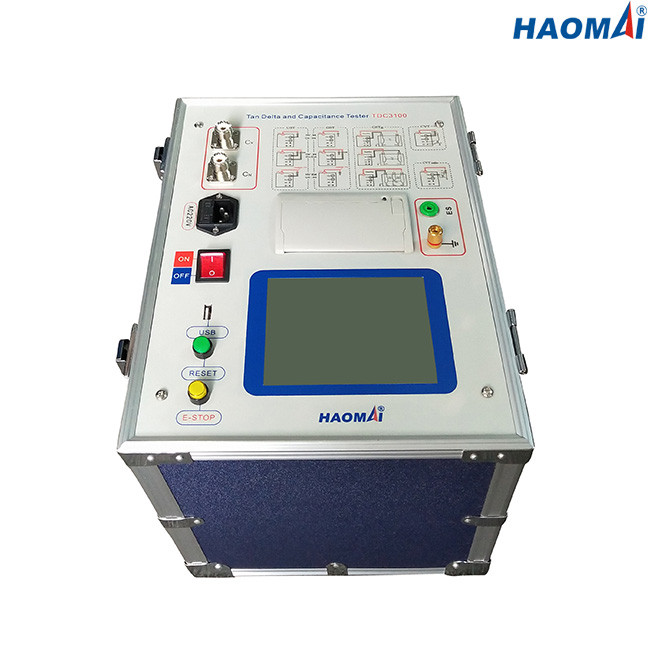
The TDC-3100 is a fully automatic 12 kV insulation power-factor / dissipation-factor (tan δ) and capacitance test set…
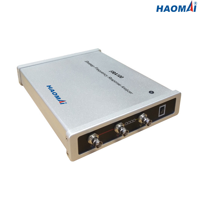
The FRA100 is a sweep frequency response analyzer (SFRA) that detects mechanical and electrical changes in the core…