
VAE-430 Software: Relay Protection Test UI
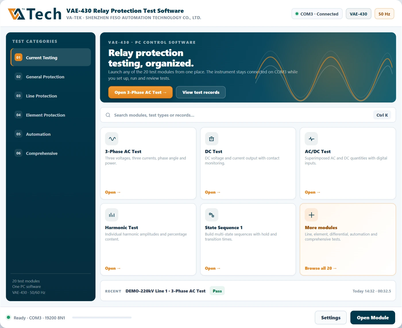
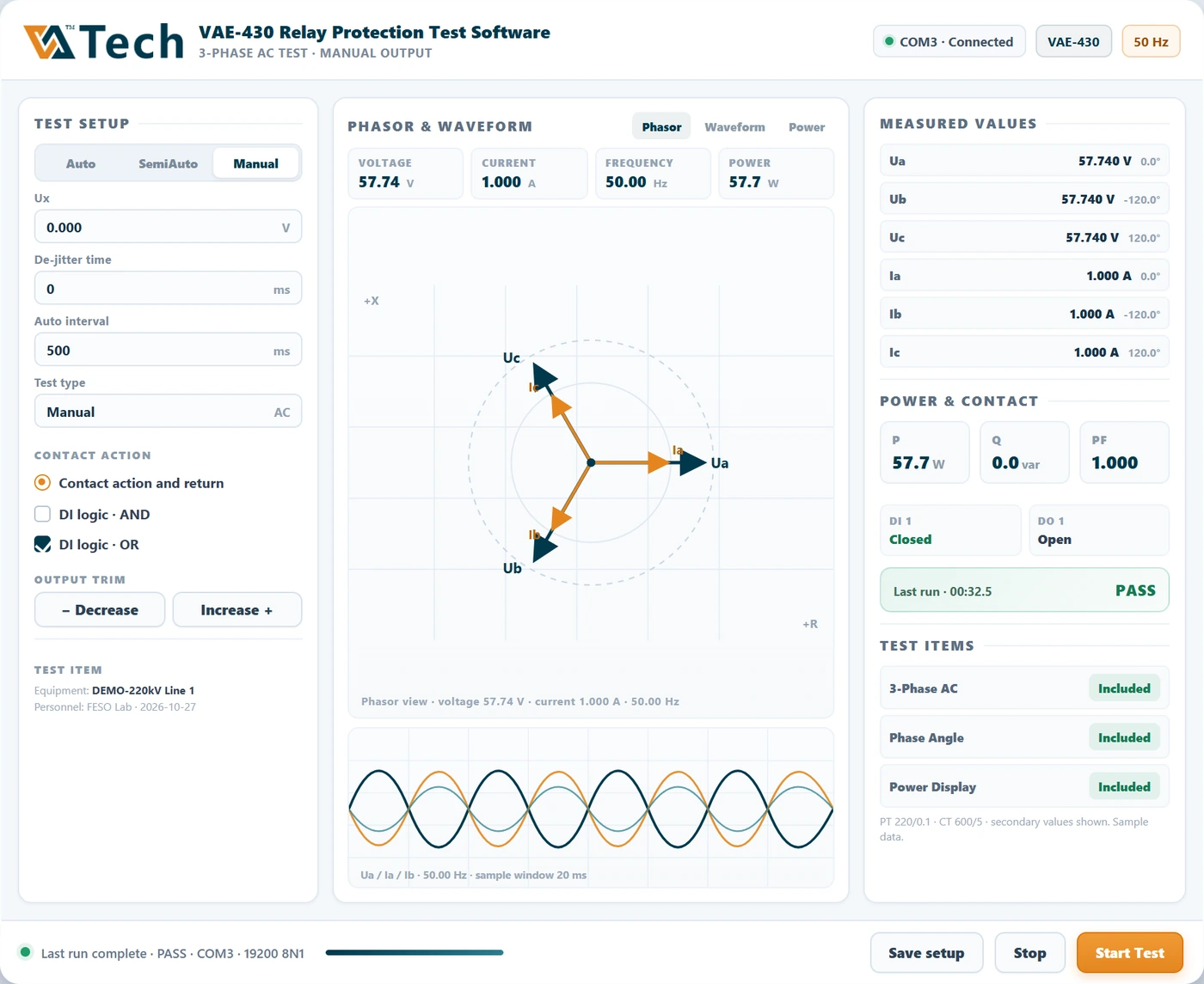
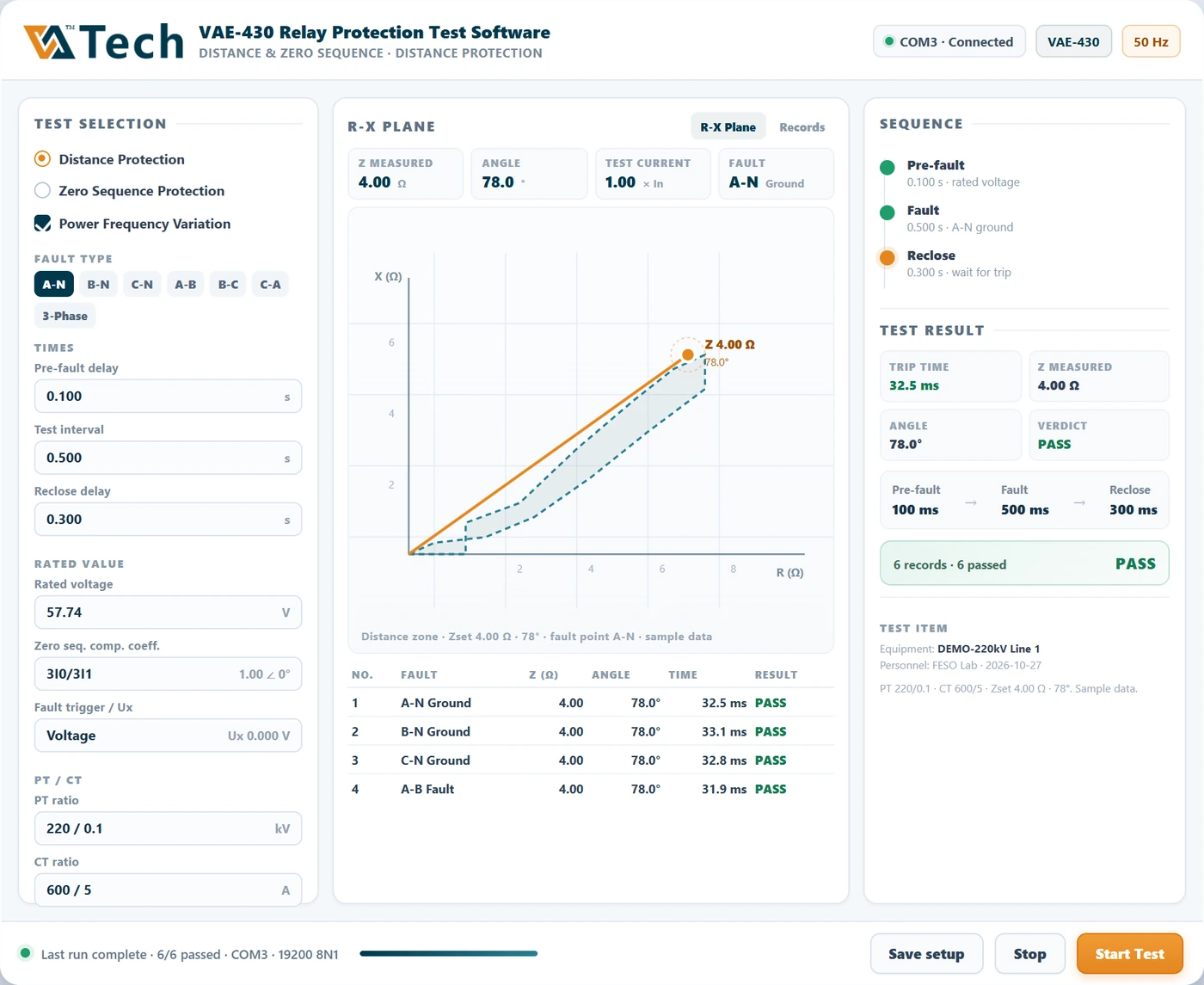
A first look at the planned VAE-430 PC software: one launcher for the test modules, a three-phase AC screen built around phasor and waveform, and a distance / zero-sequence screen that keeps the R-X plane and test records in one view.
Concept interface preview. These screens are design concepts with sample data, not screenshots of shipping software. Module set, layout and final release may differ.
Built around the test, not the menu
The VAE-430 is a three-phase relay test set: 3 × 0–40 A AC current, 4 × 0–120 V AC voltage, DC outputs, and 8 binary inputs / 4 binary outputs. The software has to keep that data visible without making the operator hunt for it. The concept below follows the same rule.
What stays the same
Three currents and four voltages, phase angle, frequency and power; PT/CT ratios; binary input and output state; manual, semi-auto and auto modes; test records that can be reviewed after the run.
What improves
Setup, measurement and result are separated into clear columns; numeric readouts are larger; status colors are consistent; the launcher adds search and recent runs instead of a long category tree.
Why show the interface at all
Protection engineers judge a test set by what happens on screen: whether the phasor matches the wiring, whether the trip time is readable, whether the record can be exported without rebuilding the test. A modern interface does not change the electrical specifications — it changes how quickly the operator can confirm them.
The final VAE-430 software will be validated against the instrument’s actual channel map, calibration data and test sequences. The screens shown here are a design direction, not a promise of a specific shipping layout.
Want the VAE-430 datasheet or a software walkthrough?
Tell us which relays and schemes you test — overcurrent, distance, zero sequence, differential or frequency — and we will confirm the configuration, lead time and price.
Request datasheet and price VAE-430 product page Compare VAE-430 and VAE-660UI concept preview · sample data · VA-TEK / Shenzhen Feso Automation Technology Co., Ltd.