 VA-TEK Engineering
A power transformer that has taken a through-fault, travelled by road, or been opened for a tap-changer repair carries no visible sign of what the movement did inside. Sweep frequency response analysis (SFRA) answers the question without removing the cover: it injects a low-voltage sweep into a winding and records how impedance changes with frequency, producing a fingerprint of the core-and-winding assembly. Compare that fingerprint with a reference, and a change in mechanical geometry appears as a change in the curve.
The test is routine at commissioning and after any event that could have moved a winding. What decides whether the result is usable is not the instrument’s sweep range but the reference it is compared against.
What SFRA measures
The sweep frequency response analysis measurement is an impedance-versus-frequency curve, normally from 10 Hz to 10 MHz. At low frequencies the core dominates; through the mid-band the winding inductance and capacitance set the shape; at high frequencies the leads, grounding and bushing capacitance take over. A deformation changes the geometry, and with it the distributed inductance and capacitance, so the resonances shift.
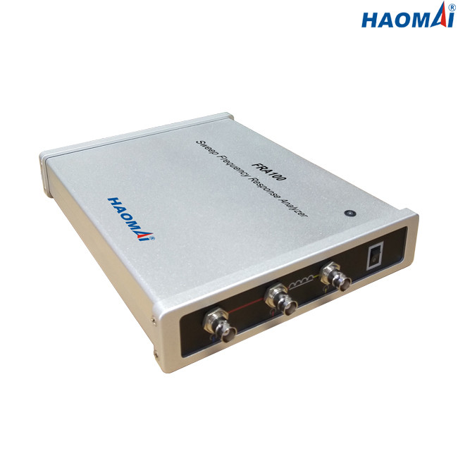
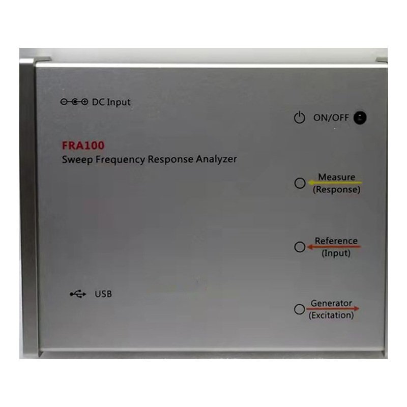
On the FRA100 the sweep runs 10 Hz–10 MHz with ≤0.001 % frequency accuracy and up to 50,000 user-defined points (600 by default), and a single winding takes about 1–2 minutes. The instrument is rated for transformers of 6 kV and above, weighs 2.3 kg and provides 5000 V isolation to protect the connected laptop — vendor data.
The three comparisons that make a curve readable
A curve on its own proves nothing. Three references are used, in descending order of strength.
Time comparison — the same winding against its own earlier measurement. This is the strongest reference because it removes every difference except the change under investigation, which is why a commissioning fingerprint matters more than any later test.
Phase comparison — the three phases of the same unit against each other. Valid for a three-limb core where the phases are magnetically similar; a five-limb core or an asymmetrical winding weakens it.
Sister-unit comparison — against an identical transformer. Useful when no baseline exists, but it assumes both units were built and measured the same way.
| Reference | What it detects | Limitation |
|---|---|---|
| Own baseline (time) | Any change since commissioning; the strongest evidence | Needs a stored fingerprint from before the event |
| Sister phases | A localized deformation when one phase differs | Weaker on five-limb cores and asymmetrical windings |
| Sister unit | Gross differences where no baseline exists | Build and measurement differences contaminate the result |
Reading the frequency bands
Deviations are read by band, because different parts of the structure dominate different ranges.
| Band | What dominates | A deviation suggests |
|---|---|---|
| Below 20 Hz | Core magnetisation | Core movement, residual magnetism, core grounding |
| 20 Hz – 2 kHz | Winding inductance | Radial or axial winding deformation, turn displacement |
| 2 – 20 kHz | Winding capacitance | Changes in winding-to-winding or winding-to-ground spacing |
| Above 20 kHz | Leads, bushings, grounding | Lead dress, grounding, bushing capacitance |
The bands are a guide, not a verdict. A shift at 50 Hz and a shift at 5 kHz can share a cause, and a clean curve does not exclude a fault that has not yet moved the geometry. SFRA is read beside turns-ratio and winding-resistance results, not instead of them.
Where SFRA sits in the test sequence
Measure at commissioning to establish the fingerprint, after transport or a through-fault, before and after any repair that opens the tank, and during periodic assessment of critical units. In the commissioning sequence it follows the insulation tests and precedes the final ratio and resistance checks, so a mechanical anomaly is known before the unit is energised. The practical pairing is with transformer turns ratio testing, which catches turns and tap problems SFRA can miss, and winding resistance testing, which catches contact and connection faults.
Frequently asked questions
Does SFRA detect a fault that turns ratio testing misses?
Yes, when the fault is mechanical rather than electrical: radial or axial winding deformation, loosened clamping and core movement change the frequency response while leaving the turns ratio unchanged. The two tests cover different failure modes and are normally reported together.
Can SFRA be done without a previous baseline?
It can, using phase comparison and a sister unit. The result is weaker: phase comparison depends on core construction, and a sister unit introduces build differences. A baseline measured at commissioning removes both problems.
How many curves does the analysis software need?
The FRA100 software loads up to nine curves and calculates the comparison parameters automatically — vendor data. In practice three phases plus a stored baseline cover most field work; extra curves help when a fleet comparison is being built.
A sweep frequency response analysis report is only as good as its reference set. Units that store a commissioning fingerprint get a definite answer after a fault; units that do not are left with phase and sister-unit comparisons and a wider margin of doubt. The FRA100 covers the measurement side, the rest of the range is listed under transformer testers, and turns ratio or tan delta results belong in the same report. To plan a test sequence for a specific unit, contact the team.