
 VA-TEK Engineering
Directional overcurrent relay testing proves that a 67 element trips only for faults in the set direction. It verifies pickup, operating time, sensitivity angle, the forward and reverse boundaries, and the CT/PT polarity that defines the polarizing quantity. The result is a relay that trips for forward faults and stays blocked for reverse faults.
Key takeaways
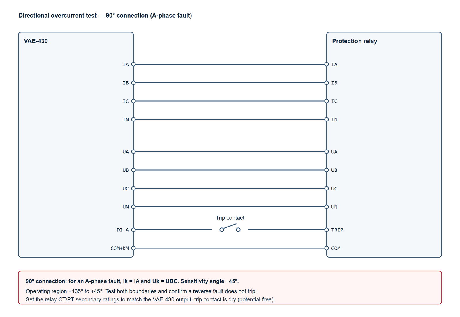
- Use a 90-degree connection. For an A-phase fault, the operating current is IA and the polarizing voltage is UBC. Repeat the same pattern for B and C phases.
- Test the angle, not only the current. A 67 element can pick up correctly and still trip in reverse if the polarizing voltage or CT polarity is wrong.
- Find both boundaries. Sweep the current angle into the forward boundary from each side and confirm the trip/no-trip transition within about 5 degrees.
- Prove the reverse block. Apply the same current at the reverse angle and confirm that the element does not trip within the published time.
- Record the reference. Note the relay angle convention: current lagging the polarizing voltage is the usual reference, but some relays use the opposite sign.
What does a directional overcurrent test prove?
A directional overcurrent element compares the phase of a current with a polarizing voltage. In a 90-degree connection, the current and voltage are chosen so that the phase relationship is close to the relay’s maximum torque angle for a forward fault. The element should operate for a forward fault and remain blocked for a reverse fault.
The test proves three separate things: the current pickup is correct, the time characteristic is correct, and the direction decision is correct. A relay can pass the first two and fail the third, which is why the angle sweep is not optional.
How do you test a 67 element?
- Isolate the relay and record the settings. Disable other protection elements that could trip during the test. Record the pickup, curve, time multiplier, sensitivity angle, and the polarizing quantity from the relay manual.
- Wire the 90-degree connection. Connect IA, IB, IC and IN to the relay current inputs. Connect UA, UB, UC and UN to the voltage inputs. Connect the relay trip contact to DI A and COM+KM on the test set.
- Set the reference. Apply rated voltage and a current below pickup. Confirm the relay measures the expected phase angle. If the angle is not what you expect, stop and check the CT/PT polarity before going further.
- Measure pickup. Hold the current at the sensitivity angle and raise it slowly. Record the pickup and the drop-out. Use 0.95 and 1.05 times the expected pickup as the no-trip and trip points.
- Measure the time. Apply twice the pickup current and record the operating time. Compare it with the curve and time multiplier in the relay settings.
- Sweep the forward boundary. Keep the current at twice pickup and move the angle in 5-degree steps through the boundary. Record the last no-trip angle and the first trip angle.
- Prove the reverse block. Apply the same current at the reverse angle and confirm that the relay does not trip. Hold it for at least the published reset time.
- Repeat for B and C. Use the corresponding current and polarizing voltage for each phase. A single-phase test does not prove the other two connections.
What settings and test points should you use?
| Setting | Example value | Test point | Expected result |
|---|---|---|---|
| Phase pickup | 1.00 A (0.2 In) | 0.95 A / 1.05 A | No trip / trip |
| Time characteristic | IEC SI, TMS 0.1 | 2 x pickup | About 1.0 s |
| Sensitivity angle | -45 degrees | -45 degrees | Trip |
| Forward boundary | -135 to +45 degrees | -140 / -130 degrees | No trip / trip |
| Forward boundary | -135 to +45 degrees | +40 / +50 degrees | Trip / no trip |
| Reverse block | +135 degrees | 2 x pickup at +135 degrees | No trip |
| Drop-out | 0.95 x pickup | Fall from 1.1 to 0.9 x pickup | Reset |
The angle limits above are for a typical -45-degree characteristic. Use the actual characteristic and angle convention in the relay manual; do not copy the numbers into a different relay family.
How do you wire the VAE-430 to the relay?
| VAE-430 terminal | Relay terminal | Note |
|---|---|---|
IA, IB, IC |
Phase current inputs | Series connection; observe the polarity dot |
IN |
Neutral current input | Return path for the three-phase set |
UA, UB, UC |
Phase voltage inputs | Phase-to-neutral; 57.735 V is common |
UN |
Voltage neutral | Common return for the voltage inputs |
DI A |
Trip contact, one side | Dry contact; the test set supplies the wetting voltage |
COM+KM |
Trip contact, other side | Common for the digital inputs |
What is the pass criterion?
Use the relay manual as the authority. For a field test, a practical criterion is:
- Pickup: within 5 percent of the setting, or the tolerance stated in the manual.
- Time: within 5 percent or 30 ms, whichever is larger, at the tested point.
- Boundary: within 5 degrees of the expected angle.
- Reverse: no trip for the full supervision time at the reverse angle.
- Repeatability: three consecutive operations at the same point should agree within the same tolerance.
Why does the relay trip in reverse or miss the boundary?
Check the polarizing voltage first. A swapped UBC/UCB connection shifts the reference by 180 degrees and turns the forward region into the reverse region. Check the CT polarity second. A reversed CT has the same effect on the current phase. Check the angle convention third. Some relays define the sensitivity angle as current lagging the voltage, others as current leading it. A 90-degree mistake in the test setup looks like a relay failure.
If the relay trips at the correct angle but the boundary is a few degrees off, confirm the test set’s angle resolution and the relay’s measurement accuracy before changing the setting. Do not adjust the relay to match a test lead error.
Frequently asked questions
Can I test a 67 element with a single current channel?
Yes. The 90-degree connection is a single-phase test: one current and one polarizing voltage. Repeat it for B and C phases. The neutral current is not needed for the directional decision in this connection.
What is the difference between 67 and 67N?
A 67 element uses phase current and a phase-to-phase polarizing voltage. A 67N element uses zero-sequence current 3I0 and zero-sequence voltage 3U0. The test method is similar, but the polarizing quantities and the angle reference are different.
Why does the relay not trip at twice pickup?
Check the time multiplier, the curve selection, and the reset time. If the relay was previously picked up, the reset timer may still be running. Also confirm that the directional element is enabled and that the polarizing voltage is above its minimum threshold.
Do I need to test the time curve at more than one point?
Test at least two points, for example 2x and 5x pickup. A single point cannot distinguish a wrong curve from a wrong time multiplier. The IDMT calculator linked below gives the expected times for the standard curves.
Can I use the VAE-430 for a 67 test on a high-voltage relay?
Yes, if the relay’s current and voltage inputs are rated for the test set’s output. The VAE-430 provides three currents and four voltages, including an independent fourth voltage. Check the relay burden and the test lead voltage drop before the test.
Where VA-TEK test sets fit
The VAE-430 provides three current channels, four voltage channels and eight digital inputs, which covers a 90-degree directional overcurrent test on a single relay. Use the independent UX channel when the relay needs a separate polarizing voltage. For the wider test sequence, start from the relay protection testing hub and the relay testing whitepaper.
Related reading: overcurrent relay testing procedure for the non-directional 50/51 element, and the IDMT curve calculator for the expected operating times.
Standards and references
- IEEE C37.112-2018 — inverse-time characteristic equations for overcurrent relays.
- IEC 60255-151:2009 — functional requirements for over/under current protection.
- IEEE C37.90-2005 — surge withstand capability of relay systems.
- Relay manufacturer’s technical manual — settings, angle convention and tolerances.
VAE-430 · relay protection test set
See the software before you buy the set
Every VAE-430 runs the same 20-module PC software. Watch it drive a three-phase AC test and a distance fault, then ask us for the test package.
- US$2,000per set, EXW
- 9interface languages
- 7 daysdelivery
- Includedfull test software
Field-commissioning workflows, IEC and IEEE time curves, COMTRADE playback and a full DI/DO matrix — on one PC, with no per-module licence.
Request the software test package
Tell us which relay family you test. We reply with pricing, lead time and the matching setup files within one business day.
