
 VA-TEK Engineering
A busbar protection charging test proves that the 87B scheme is stable when the busbar is energized and that the CT secondary circuits and trip matrix are correct. It verifies the check zone, the CT polarity, the differential current, and the trip outputs before the busbar carries load.
Key takeaways
- Charging means energizing without load. The test proves the scheme is stable when the busbar is energized and the CTs see only the charging current.
- CT circuits are the usual fault. An open, shorted, or reversed CT secondary is more common than a relay setting error. Check the circuits first.
- Check zone is separate. The check zone must not trip for a fault outside the busbar, and it must allow the busbar zone to trip for a fault inside.
- Trip matrix is part of the test. Every feeder breaker must receive the correct trip command; a correct differential element with a wrong matrix does not clear the busbar.
- Primary injection is the reference. Secondary injection proves the relay; primary injection proves the CT circuits and the ratio.
What does a busbar charging test prove?
A busbar protection scheme compares the sum of the feeder currents with the busbar voltage or uses a high-impedance differential. During charging, the busbar is energized with no load, and the only current is the capacitance current of the busbar and connected equipment.
The charging test proves that the differential current is below the pickup, the CT circuits are correct, the check zone is stable, and the trip matrix is correct. It is usually performed before the busbar is put into service and repeated after any CT circuit modification.
How do you run a busbar charging test?
- Review the scheme. Note the busbar zones, the check zone, the CT ratios, the CT polarity, and the trip matrix.
- Inspect the CT circuits. Check for open circuits, shorting links, and correct polarity at each feeder. Confirm the CT secondary grounding.
- Isolate the trip outputs. Disconnect the trip circuits from the breakers or use the test mode, and confirm the isolation.
- Energize the busbar. Close the incoming breaker with no load. Measure the charging current and the differential current.
- Confirm stability. The 87B element must not pick up. Record the differential current and compare it with the pickup.
- Test the check zone. Inject a current that represents a fault outside the busbar and confirm that the check zone does not trip. Then inject a fault inside and confirm the trip.
- Verify the trip matrix. Confirm that each feeder breaker receives the correct trip command for its zone.
- Record the results. Note the charging current, the differential current, the CT secondary currents, and the trip outputs.
What settings and test points should you use?
| Setting | Example value | Test point | Expected result |
|---|---|---|---|
| Differential pickup | 0.2 In | Charging current | No trip |
| CT ratio | 2000/1 | Primary injection | Correct secondary |
| CT polarity | All feeders toward the busbar | Primary injection | Correct sum |
| Check zone pickup | 0.1 In | External fault | No trip |
| Busbar zone | 0.2 In | Internal fault | Trip |
| Trip matrix | All feeder breakers | Internal fault | Correct outputs |
| CT supervision | If used | Open CT | Alarm |
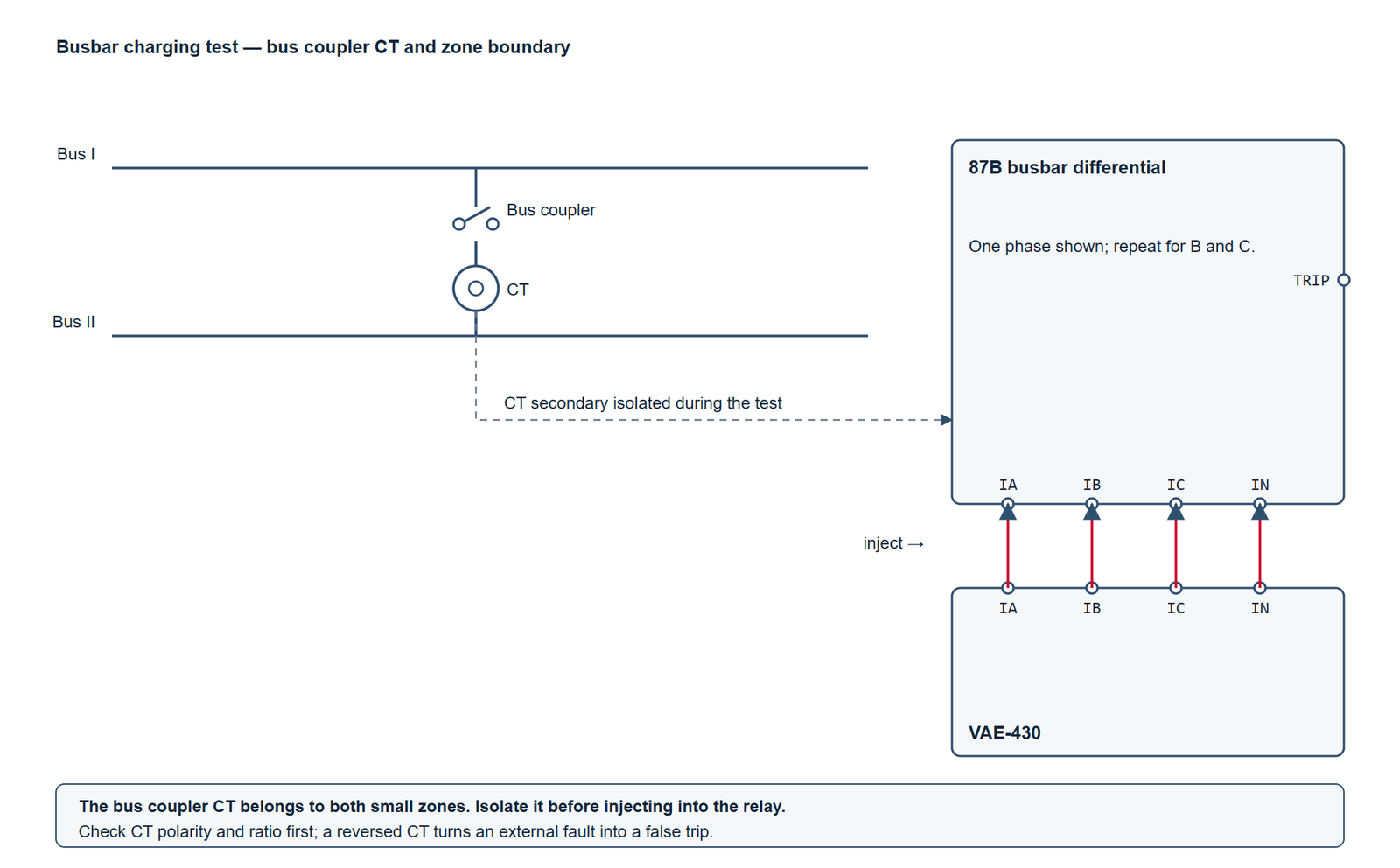
How do you wire the VAE-430 for the test?
| VAE-430 terminal | Test point | Note |
|---|---|---|
IA |
87B relay current input | Secondary injection into the differential path |
IN |
Relay current neutral | Return path |
DI A |
Trip contact | Dry contact from the relay |
DI B |
Check zone trip contact | Use a second input if the outputs are separate |
COM+KM |
Contact common | Common for the digital inputs |
For a primary injection test, use a primary injection set between the busbar and the feeder CT, with the busbar isolated. The VAE-430 is a secondary test set; it proves the relay and the secondary wiring, not the CT ratio or the primary circuit.
What is the pass criterion?
- Stability: no trip during charging, with the differential current below the pickup.
- CT circuits: correct polarity, continuity, and grounding at every feeder.
- Check zone: no trip for an external fault, trip for an internal fault.
- Trip matrix: every breaker receives the correct command.
- CT supervision: alarm for an open CT, if the scheme uses it.
Why does the 87B element trip during charging, or fail to trip on a fault?
Trip during charging: a CT secondary may be shorted, a polarity may be reversed, or the differential pickup may be too low for the charging current. Check the CT circuits before changing the setting.
No trip on a fault: the trip matrix may be wrong, the check zone may block the busbar zone, or the CT circuit may be open. Confirm the output matrix and the check zone logic.
Check zone trips for an external fault: the check zone may be misconfigured or a CT may be assigned to the wrong zone. Check the zone assignment, not only the pickup.
CT supervision alarm: an open CT secondary can produce a differential current. Investigate the alarm before the charging test.
Frequently asked questions
What is a busbar charging test?
It is the test performed when the busbar is energized with no load. The only current is the charging current, so the differential element should remain stable. It proves the CT circuits and the scheme before the busbar carries load.
Can I replace the charging test with secondary injection?
Secondary injection proves the relay and the secondary wiring, but it does not prove the CT ratio, the CT polarity in the primary circuit, or the actual charging current. Use both: secondary injection before energization, charging test at energization.
Why is the check zone needed?
The check zone supervises the busbar zone and prevents a trip for a fault outside the busbar. It must be stable for an external fault and must allow the busbar zone to trip for an internal fault.
What is the most common busbar protection error?
A CT circuit error: an open secondary, a shorting link left in place, or a reversed polarity. These errors produce a differential current or a missing current and are found by the CT circuit check and the primary injection test.
How often should the charging test be repeated?
After any CT circuit modification, after a relay replacement, and at the commissioning of a new busbar. Routine testing follows the owner’s maintenance policy.
Where VA-TEK test sets fit
The VAE-430 provides the secondary currents for the 87B relay and the digital inputs for the trip and check zone contacts. For CT ratio and polarity checks, the VACTP200P CT/PT analyzer measures the excitation curve and the ratio. Start with the relay protection testing hub.
Related reading: busbar protection testing for the zone and check zone tests, and primary vs secondary injection testing for the injection method.
Standards and references
- IEEE C37.234-2021 — guide for protective relay applications to power system buses.
- IEEE C57.13-2016 — standard requirements for instrument transformers.
- IEC 60255-121:2014 — functional requirements for distance protection (reference for zone logic).
- Relay manufacturer’s technical manual — busbar zone and check zone logic.
VAE-430 · relay protection test set
See the software before you buy the set
Every VAE-430 runs the same 20-module PC software. Watch it drive a three-phase AC test and a distance fault, then ask us for the test package.
- US$2,000per set, EXW
- 9interface languages
- 7 daysdelivery
- Includedfull test software
Field-commissioning workflows, IEC and IEEE time curves, COMTRADE playback and a full DI/DO matrix — on one PC, with no per-module licence.
Request the software test package
Tell us which relay family you test. We reply with pricing, lead time and the matching setup files within one business day.
