
 VA-TEK Engineering
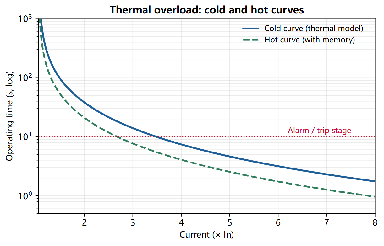
Thermal overload relay testing proves that the 49 element models the motor or transformer heating correctly, trips on the cold and hot curves at the set time, and respects the thermal memory after a trip. It verifies the pickup, time constant, cooling, alarm and trip outputs.
Key takeaways
- Cold and hot are different tests. A cold curve starts from ambient; a hot curve starts from a preheated state. The relay must trip earlier on the hot curve.
- Thermal memory is the point. After a trip, the relay must remember the heat and cool down according to the thermal model, not reset instantly.
- Test at more than one current. A single point does not prove the curve shape or the time constant.
- Alarm before trip. The alarm stage gives the operator warning before the trip; test it separately.
- Cooling is part of the model. A relay that cools too fast allows a restart while the motor is still hot.
What does a thermal overload test prove?
A thermal overload element models the temperature of the protected equipment from the current history. It uses a thermal time constant, a pickup current, and a hot/cold ratio to calculate the trip time. The model includes a cooling behavior when the current is removed.
The test proves the pickup, the cold curve, the hot curve, the thermal memory, the cooling time constant, the alarm stage, and the trip output. It does not prove the short-circuit protection; test the overcurrent elements separately.
How do you test a 49 element?
- Record the settings. Note the pickup current, thermal time constant, hot/cold ratio, alarm threshold, cooling time constant, and trip output.
- Start from a cold state. Confirm that the relay’s thermal state is at ambient or use the relay’s reset command.
- Apply 1.5x pickup. Measure the trip time and compare it with the cold curve.
- Apply 2x pickup. Measure the trip time at a second point to prove the curve shape.
- Test the hot curve. Preload the relay at pickup for a set time, then apply the test current and measure the trip time. The hot trip time must be shorter than the cold time.
- Test the thermal memory. After a trip, reduce the current to zero for a short time, then reapply the test current. The relay must trip earlier than a cold start.
- Test the cooling. Leave the relay at zero current for the cooling time constant and confirm that the thermal state returns to the expected value.
- Test the alarm. Apply a current above the alarm threshold but below the trip threshold and confirm the alarm output and its delay.
What settings and test points should you use?
| Setting | Example value | Test point | Expected result |
|---|---|---|---|
| Pickup | 1.05 In | 1.00 In / 1.10 In | No trip / trip |
| Thermal time constant | 30 min | 2 x pickup | Per cold curve |
| Hot/cold ratio | 0.5 | Preload 1.0 In | Hot trip earlier |
| Time at 1.5x | Per curve | 1.5 x pickup | Per curve |
| Time at 2x | Per curve | 2 x pickup | Per curve |
| Alarm threshold | 90 percent | 85 percent / 95 percent | No alarm / alarm |
| Cooling time constant | 60 min | Zero current | Per model |
How do you wire the VAE-430 to the relay?
| VAE-430 terminal | Relay terminal | Note |
|---|---|---|
IA, IB, IC |
Phase current inputs | Balanced three-phase current |
IN |
Current neutral | Common return |
DI A |
Trip contact | Dry contact from the relay |
DI B |
Alarm contact | Optional; use if the relay has a separate alarm |
COM+KM |
Contact common | Common for the digital inputs |
The thermal test can take minutes, especially at 1.5x pickup with a long time constant. Use the test set’s timed output and a stable current source; do not rely on a handheld source that drifts.
What is the pass criterion?
- Pickup: within 3 percent of the setting.
- Cold curve: within 10 percent or the relay manual tolerance.
- Hot curve: shorter than the cold time and within the model prediction.
- Thermal memory: the post-trip trip time is shorter than a cold start.
- Cooling: the thermal state follows the cooling time constant.
- Alarm: correct threshold, delay, and output.
Why does the relay trip too early or too late?
Thermal state not reset. A previous test left heat in the model. Reset the thermal state or wait for the cooling time before the cold test.
Wrong hot/cold ratio. The ratio changes the hot curve. Confirm the setting against the motor data, not against a generic value.
Ambient temperature input. Some relays use an ambient temperature or a separate RTD input. A wrong ambient value shifts the entire model.
Alarm stage active. The relay may have tripped on the alarm stage or a separate overload element. Read the event log to see which stage operated.
Frequently asked questions
What is the difference between the cold curve and the hot curve?
The cold curve starts from ambient temperature; the hot curve starts from a preheated state. The hot curve trips earlier because the equipment has less thermal margin. Both curves must be tested.
What is thermal memory?
The relay remembers the heat from the previous load or trip and uses it in the next calculation. Without memory, a relay would allow a restart while the motor is still hot, which can damage the insulation.
Why test at 1.5x and 2x instead of one point?
Two points prove the curve shape and the time constant. A single point can pass with a wrong time constant if the test current happens to match the curve at that point.
How long does a thermal test take?
It depends on the time constant. A 30-minute time constant at 1.5x pickup can take several minutes per point. Plan the test time and use the relay’s thermal state display to confirm the start condition.
Can I test the 49 element with a single current?
Yes if the relay uses a single-phase thermal model. For a three-phase motor protection relay, use a balanced three-phase current and confirm that all three phases contribute to the model.
Where VA-TEK test sets fit
The VAE-430 provides a stable three-phase current for the thermal test, with timed outputs for long-duration tests. Start with the relay protection testing hub and the relay testing whitepaper.
Related reading: motor protection relay testing for the complete motor scheme, and transformer differential protection testing for the transformer thermal element.
Standards and references
- IEC 60255-149:2013 — functional requirements for thermal electrical relays.
- IEEE C37.96-2012 — guide for AC motor protection.
- IEEE C37.91-2021 — guide for protective relay applications to power transformers.
- Relay manufacturer’s technical manual — thermal model and time constants.
VAE-430 · relay protection test set
See the software before you buy the set
Every VAE-430 runs the same 20-module PC software. Watch it drive a three-phase AC test and a distance fault, then ask us for the test package.
- US$2,000per set, EXW
- 9interface languages
- 7 daysdelivery
- Includedfull test software
Field-commissioning workflows, IEC and IEEE time curves, COMTRADE playback and a full DI/DO matrix — on one PC, with no per-module licence.
Request the software test package
Tell us which relay family you test. We reply with pricing, lead time and the matching setup files within one business day.
