
 VA-TEK Engineering
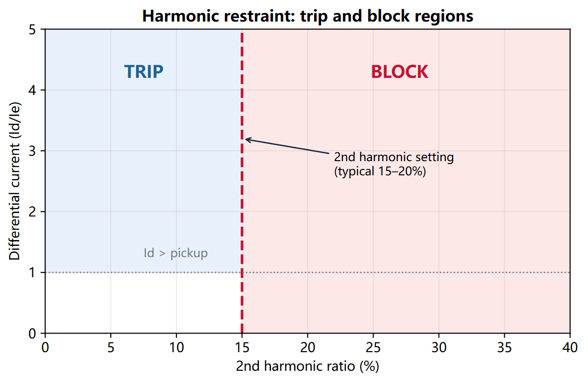
Transformer differential harmonic restraint testing proves that the 87T relay blocks tripping when the second or third harmonic ratio exceeds the setting, and trips when the ratio is below it. It verifies the harmonic thresholds, the ratio calculation, cross-blocking, and the trip time.
Key takeaways
- Harmonic restraint is a ratio. The relay compares the harmonic current with the fundamental differential current; it does not block on the absolute harmonic current alone.
- 2nd harmonic is for inrush. A high second-harmonic ratio is the classic sign of transformer energization. The relay should block during inrush and trip for an internal fault.
- 3rd harmonic is for overexcitation. A high third-harmonic ratio can indicate overexcitation; some relays use it as a separate blocking or alarm element.
- Test the threshold from both sides. Apply a ratio just below and just above the setting and confirm the trip/block transition.
- Cross-blocking matters. If the relay uses one phase to block the others, test a single-phase harmonic injection and confirm the expected behavior.
What does a harmonic restraint test prove?
A transformer differential relay calculates a differential current from the currents on both sides of the transformer. During energization, the magnetizing inrush current contains a large second-harmonic component, which can cause a false differential trip. Harmonic restraint blocks the trip when the harmonic ratio is above the setting.
The test proves that the relay calculates the harmonic ratio correctly, blocks at the set threshold, trips below it, and applies the correct cross-blocking logic. It also proves that the harmonic filter does not delay the trip for an internal fault beyond the published time.
How do you test harmonic restraint?
- Record the settings. Note the 2nd and 3rd harmonic thresholds, the differential pickup, the slope, the cross-blocking mode, and the harmonic filter type.
- Connect the currents. Use a six-current test set for a three-phase, two-side injection. If the relay supports single-side injection in test mode, follow the relay manual.
- Establish a differential current. Inject a fundamental differential current above the pickup so that the relay would trip without restraint.
- Add the 2nd harmonic. Raise the second-harmonic component until the relay blocks. Record the ratio at the transition.
- Check the trip side. Reduce the second-harmonic ratio below the threshold and confirm that the relay trips at the expected time.
- Repeat for the 3rd harmonic. Use the same procedure with the third-harmonic component and the 3rd harmonic setting.
- Test cross-blocking. Inject the harmonic into one phase and confirm whether the relay blocks only that phase or all phases, as configured.
- Record the time. Measure the trip time below the threshold and the block time above it.
What settings and test points should you use?
| Setting | Example value | Test point | Expected result |
|---|---|---|---|
| 2nd harmonic threshold | 15 percent | 10 percent / 20 percent | Trip / block |
| 3rd harmonic threshold | 20 percent | 15 percent / 25 percent | Trip / block |
| Differential pickup | 1.0 Ie | 0.95 Ie / 1.05 Ie | No trip / trip |
| Slope | 0.3 | 2 x pickup | Stable |
| Block delay | 0.1 s | Step change | No trip before 0.1 s |
| Cross-blocking | All phases | Single-phase harmonic | All phases blocked |
| Trip time | 0.05 s below threshold | 2 x pickup | 0.05 s |
How do you wire the VAE-660 to the relay?
| VAE-660 terminal | Relay terminal | Note |
|---|---|---|
IA, IB, IC, IN |
HV-side current inputs | First current set; observe polarity |
Ia, Ib, Ic, In |
LV-side current inputs | Second current set; observe polarity |
DI A |
Trip contact | Dry contact from the relay |
COM+KM |
Trip contact common | Common for the digital inputs |
For a single-side harmonic test, use the VAE-430 with the relay in test mode and inject the harmonic component into the differential current path. Confirm the relay’s harmonic calculation with its metering before the trip test.
What is the pass criterion?
- 2nd harmonic threshold: within 2 percent of the setting.
- 3rd harmonic threshold: within 2 percent of the setting.
- Trip below threshold: trip within the published time.
- Block above threshold: no trip for the full block delay.
- Cross-blocking: matches the configured mode.
- Repeatability: three transitions at the same threshold within 1 percent.
Why does the relay block on a balanced load or trip during inrush?
Block on balanced load: the harmonic measurement may be picking up noise from the test leads, or the relay may be in a test mode that forces the harmonic ratio. Check the harmonic metering with a pure fundamental current.
Trip during inrush: the second-harmonic threshold may be too low, the harmonic filter may be disabled, or the inrush current may not contain enough second harmonic because of the transformer design. Record the harmonic ratio during the actual energization and compare it with the setting.
No trip on an internal fault: the harmonic ratio may be above the threshold because of CT saturation or a fault-induced harmonic. Check the waveform and the relay event log; do not simply raise the threshold.
Frequently asked questions
Why does the relay use the second harmonic for inrush?
Transformer inrush current is rich in second harmonic because of the non-linear magnetizing characteristic. An internal fault current is usually rich in fundamental and may contain some second harmonic, but the ratio is lower. The relay uses the ratio to distinguish the two.
What is the difference between harmonic restraint and harmonic blocking?
Harmonic restraint adds a restraining quantity to the differential characteristic; harmonic blocking inhibits the trip when the harmonic ratio exceeds a threshold. Many relays use the terms interchangeably, but the logic and the test points can differ. Read the relay manual.
Can I test harmonic restraint with a single current channel?
Only if the relay supports a single-side test mode and calculates the harmonic ratio from that current. For a full three-phase, two-side test, use a six-current set such as the VAE-660.
Why does the 3rd harmonic threshold matter?
Overexcitation produces a high third-harmonic component. Some relays use a 3rd harmonic element to block or alarm during overexcitation, and the threshold must be tested separately from the 2nd harmonic inrush restraint.
How do I generate a harmonic current with a test set?
Use the harmonic superposition function in the test set (the 0004 module on the VAE-430) or the harmonic output in the six-current software. Set the fundamental and harmonic amplitudes and confirm the ratio with the relay metering.
Where VA-TEK test sets fit
The VAE-660 provides six currents for a three-phase, two-side harmonic restraint test. For a single-side test, the VAE-430 with the 0004 harmonic module can generate the required fundamental and harmonic components. Start with the relay protection testing hub and the relay testing whitepaper.
Related reading: transformer differential protection testing for the bias and stability tests, and when to use six-phase relay testing for the channel-count decision.
Standards and references
- IEEE C37.91-2021 — guide for protective relay applications to power transformers.
- IEEE C57.13-2016 — standard requirements for instrument transformers.
- IEC 60255-151:2009 — functional requirements for over/under current protection.
- Relay manufacturer’s technical manual — harmonic restraint logic and thresholds.
VAE-430 · relay protection test set
See the software before you buy the set
Every VAE-430 runs the same 20-module PC software. Watch it drive a three-phase AC test and a distance fault, then ask us for the test package.
- US$2,000per set, EXW
- 9interface languages
- 7 daysdelivery
- Includedfull test software
Field-commissioning workflows, IEC and IEEE time curves, COMTRADE playback and a full DI/DO matrix — on one PC, with no per-module licence.
Request the software test package
Tell us which relay family you test. We reply with pricing, lead time and the matching setup files within one business day.
