
 VA-TEK Engineering
CT saturation testing measures the excitation curve and the knee point of a current transformer, then compares the available secondary voltage with the burden and the fault current. It proves that the CT does not saturate before the protection operates and that the relay remains stable.
Key takeaways
- The knee point is a definition. IEC and IEEE use different definitions; record which one the test set uses and compare like with like.
- Burden matters as much as the CT. A CT that passes on its own can saturate with the actual relay, wiring, and test leads connected.
- Calculate before you test. The required secondary voltage is the fault current times the total burden. Compare it with the excitation curve.
- Class P and class 5P are different. A protection CT has a composite error and an accuracy limit factor; a metering CT does not.
- Saturation is not always a failure. Some relays are designed to remain stable with a saturated CT; prove the relay behavior, not only the CT curve.
What does a CT saturation test prove?
A current transformer transforms current accurately only while its core is not saturated. Above the knee point, a small increase in primary current produces a large increase in excitation current, and the secondary current no longer follows the primary current.
The test proves the excitation curve, the knee point, the secondary winding resistance, and the burden. It also proves that the protection relay remains stable for a close-in fault that may saturate the CT, or that it trips correctly if the scheme depends on the CT accuracy.
How do you test CT saturation?
- Isolate the CT. Open the primary circuit, short the secondary at the CT, and disconnect the relay. Follow the site isolation procedure.
- Measure the secondary resistance. Use a micro-ohmmeter or the CT analyzer’s resistance test. Record the value at the CT terminals.
- Run the excitation test. Apply a voltage to the secondary and record the current at each voltage step. Increase the voltage until the current rises sharply.
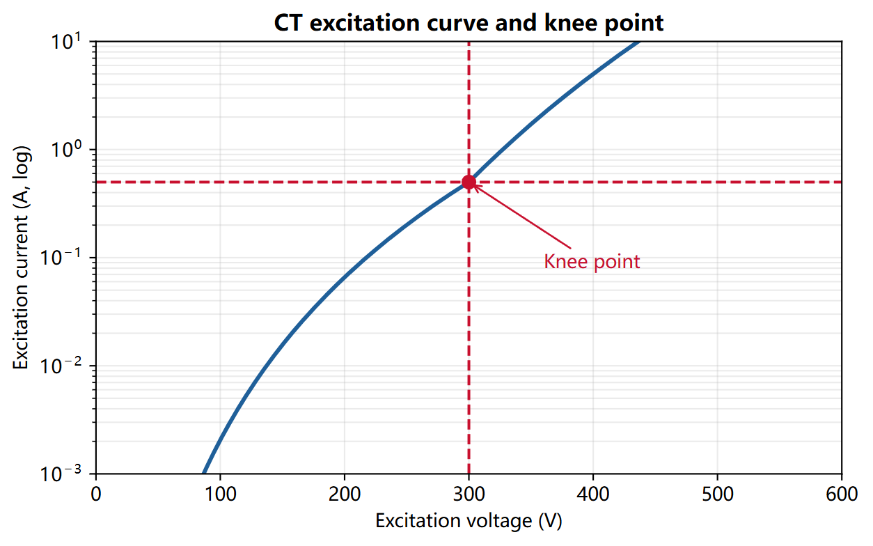
- Find the knee point. Apply the definition used by the test set or the standard. Record the voltage and the current at the knee.
- Calculate the burden. Add the relay burden, the wiring resistance, and the test leads. Compare the total with the CT rated burden.
- Calculate the required voltage. Multiply the maximum fault current by the total burden. Compare with the excitation curve at the knee.
- Reconnect the relay. Restore the secondary circuit, remove the shorting link, and confirm the CT supervision or the relay metering.
- Test the relay stability. Inject a current that represents a saturated CT and confirm that the relay does not trip for an external fault.
What settings and test points should you use?
| Quantity | Example value | Test point | Expected result |
|---|---|---|---|
| CT ratio | 2000/1 | Primary injection | Correct secondary |
| Secondary resistance | 2.0 ohm | DC resistance | Within nameplate |
| Knee point voltage | 300 V | Excitation curve | Per nameplate |
| Knee point current | 0.5 A | Excitation curve | Per nameplate |
| Relay burden | 1.0 VA | At rated current | Within CT rating |
| Total burden | 1.0 ohm | Relay plus wiring | Below CT rating |
| Required voltage | 20 kA x 1.0 ohm / ratio | Close-in fault | Below knee |
How do you wire the CT analyzer?
| Test set terminal | CT terminal | Note |
|---|---|---|
| Voltage output | Secondary winding | Excitation test; start at low voltage |
| Current input | Secondary winding | Measure the excitation current |
| Resistance input | Secondary winding | DC resistance test |
| Ground | CT secondary ground | One point of the secondary is grounded |
Use the VACTP200P CT/PT analyzer for the excitation, ratio, and polarity tests. The VAE-430 is a relay test set; it can prove the relay stability but it is not a CT excitation source.
What is the pass criterion?
- Ratio: within the CT accuracy class.
- Secondary resistance: within 10 percent of the nameplate or the design value.
- Knee point: within 10 percent of the nameplate.
- Burden: below the CT rated burden.
- Required voltage: below the excitation curve at the maximum fault current.
- Relay stability: no trip for an external fault with a saturated CT.
Why does the CT saturate, or why does the relay trip on an external fault?
High burden. Long secondary wiring, a high relay burden, or a loose connection increases the voltage drop and saturates the CT earlier. Measure the total burden, not only the relay.
DC offset. A fault current with a DC offset can saturate the CT even when the symmetrical current is below the knee. The required voltage calculation must include the offset factor.
Remanence. A CT that has been subjected to a fault may retain flux and saturate earlier on the next fault. Some schemes use a demagnetizing procedure.
Wrong CT class. A metering CT or a low-accuracy protection CT may not have the required accuracy limit factor. Check the nameplate before the test.
Frequently asked questions
What is the knee point of a CT?
The knee point is the point on the excitation curve where a small increase in voltage produces a large increase in current. IEC and IEEE define it differently; record the definition and the test method with the result.
Why is CT saturation a problem for protection?
A saturated CT produces a distorted secondary current. The relay may see a lower current, a phase shift, or a harmonic-rich waveform, which can delay the trip or cause a false trip in a differential scheme.
Can I test CT saturation with the VAE-430?
No. The VAE-430 is a relay test set with a limited voltage output; it is not a CT excitation source. Use a dedicated CT/PT analyzer such as the VACTP200P for the excitation curve.
What is the difference between class P and class 5P?
Class P is a protection CT defined by its knee point and resistance; class 5P is defined by a composite error at the accuracy limit factor. They use different test methods and different acceptance criteria.
Does a saturated CT always cause a protection failure?
No. Some relays use saturation detection or a biased characteristic to remain stable. The test must prove the relay behavior with the actual CT and burden, not only the CT curve.
Where VA-TEK test sets fit
The VACTP200P measures the CT excitation curve, ratio, polarity, and secondary resistance. The VAE-430 proves the relay stability with the actual burden. Start with the relay protection testing hub and the relay testing whitepaper.
Related reading: CT/PT excitation and knee point for the measurement procedure, and primary vs secondary injection testing for the injection method.
Standards and references
- IEC 61869-2:2012 — instrument transformers, current transformers.
- IEEE C57.13-2016 — standard requirements for instrument transformers.
- IEC 60044-1:2003 — current transformers (legacy reference for class P).
- Relay manufacturer’s technical manual — CT requirements and saturation detection.
VACTP200P · relay protection test set
Spec the CT/PT analyzer against your test list
Ratio, excitation, polarity and winding resistance in one 9 kg case. Tell us the CT and PT classes you work with and we send the matching test templates.
- 1–30000turns ratio range
- ±0.05%ratio accuracy
- ≤40 kVknee-point test
- 9 kgcarry weight
Field-commissioning workflows, IEC and IEEE time curves, COMTRADE playback and a full DI/DO matrix — on one PC, with no per-module licence.
Request the datasheet and test templates
Tell us the CT/PT types you test. We reply with the datasheet, price and test templates within one business day.
